So often, I step on a boat to find EVERY battery switch on the boat set to the 1+2, or the ALL position. In conjunction, almost never, is there a placard (beyond the actual switch labeling) showing what the normal operation and setting of those switches should be. With the manifestation of 3,4, and even 5 engine boats now, this becomes a more confusing and potentially distressing situation.
Let me be very clear - as a marine electrician, when I step on your boat and see those switches, without a placard describing proper operation, I know barely more than you (beyond obvious labeling) as to what those switches actually control or how they are wired. It’s a shame that something so mission critical goes so commonly completely unexplained by the person that wired it. Sometimes, a valid explanation is offered in an owner’s manual. Wherever that may be located.
Fret not. With a meter and a little time, absolute clarity is achievable. I am a huge fan of K.I.S.S. Not the rock bank. Keep It Simple Stupid. The easier and more simple something is to use and operate, almost definitively, the easier it is to work on, use, maintain, and pay for.
First, a few terms.
Battery Bank - one or more batteries wired together in either series (for greater than nominal (usually 12 volts) or parallel (for greater capacity (run things longer and/or run bigger things)). A bank is generally defined by it’s purpose, and, for the most part, is designed to be operated stand alone.
House Bank - usually powers “House” loads, lights, pumps, etc.
Engine Bank - powers a specific engine, port, starboard, etc.
Electronics Bank - a dedicated bank specifically for the vessels electronics- rarely a bad idea.
Battery Switch - a switch that is designed to be wired (usually) to select the source of power for the load (Port Engine, House, Electronics, etc.), while at the same time allowing for all power to that load to also be shut off completely.
ACR, Combiner, Charging Relay or Solenoid - a device that monitors the voltage (usually on 2 banks, but depending on the system can be mulitple) to either combine or disconnect the connection between those banks, usually to allow one charging device to charge both banks, or, in the case of dropping voltage (loads turned on) to disconnect those banks so as to prevent the turned on loads from depleting both banks. These operate at set (sometimes programmable) voltages with a built in logic - when I see this voltage, I do this. ACR- automatic charging relay. A relay is nothing more than an electrically controlled switch.
The most common battery switch on boats under roughly 60’ is the (4) position switch, denoted OFF, 1, 2, and 1+2. BlueSea has a switch that functionally accomplishes almost (one less capability) the same thing this switch does, but has 3 positions, OFF, ON, and COMBINE BATTERIES with a yellow caution label next to it. I like the simplicity of this switch, but it can be confusing to the end user as to what they are actually doing when they turn it on. Credit to Blue Sea for engineering it. The missing placard (responsibility of the electrician, not BlueSea) would make it very clear.
Depending on the type and style of battery switch, it can be wired a multitude of ways. Careful attention has to be given when wiring it. Many times, these switches are located in tight quarters. One wrong connection, and it will not function as engineered or designed.
Let’s focus on that dreaded most common OFF, 1, 2, 1+2 switch for a moment. As I explain it, I hope to convey the dire need for an operation placard. OFF - pretty straight forward here, the load is turned off, has no power going to it. 1 - usually connects our load to a bank. 2 - usually connects our load to a different bank. 1+2 - connects our load to both banks while also connecting both banks to each other. Simple, right? Yes, until we ask a few questions. Which bank is bank 1? Which bank is bank 2? If I have 3 of these switches, and 3 banks, now what? There is no 3 position…. What if I have 3 of these switches and 4 or 5 banks on the boat? Wait, how many banks do I even have? Nobody, short of the guy that wired it (and unfortunately, maybe not even him, because he just did what he was told and didn’t engineer the system) can answer these questions definitively just stepping onto the boat.
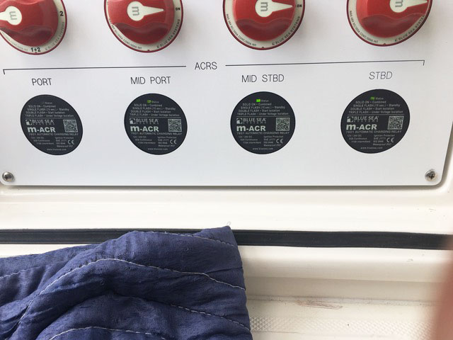
Before we come to clarity, let’s confuse things a bit more, shall we? Remember the ACR’s? They allow one bank that is being charged to combine with another so as to charge both banks and/or disconnect to prevent both from being discharged. These are rarely labeled, and when they are, even more rarely labeled in a way that provides clear understanding. Add to that, while BlueSea usually provides as part of their device a monitoring function (very sophisticated- a little light that says I’m on/combined), I don’t know if I’ve ever seen any installation actually utilize that feature. So take your 3 switches that you have no real idea what they are actually connecting, and add 2 ACR’s that you can’t see and don’t know if they are working as intended. What could possibly go wrong? Now, consider 8 switches and 4 ACR’s for 6 banks to power 4 engines, a generator, house, electronics, and a bow thruster.
A great place to start with the answers to these questions is, at the beginning, design intent. Hopefully our system was designed with the following design intentions: First, allow all loads to be turned on and off from an appropriately sized bank. Second, provide the ability for all banks to be charged. Third, in case of emergency (dead bank), allow an available bank to “jump start” another bank. Other considerations include isolation of banks that we wouldn’t want combined, or the ability to “rotate” banks. For instance, we wouldn’t want a bow thruster bank (where the thruster draws 500 amps) to be connected with anything else at that operational moment. That type of draw could wreak havoc with an engine computer or onboard electronics and produce undesired results. In a smaller boat, perhaps we may want to “rotate” our house draws from day to day between 2 different banks. Generally, it is preferable to keep engine banks “dedicated”, meaning they only provide power for the engine, with no other loads (i.e. nothing else to draw them down).
In an effort to make things easier or simpler for their owners, some installers have opted for electronic battery switches (a toggle switch controls the actual battery switch located somewhere else) in unison with a set of ACR’s to make all design intent goals mentioned above “automatic”. While that is definitely possible, without a clear and proper explanation somewhere as to the design intent, and no indication mechanism in place, it becomes counterintuitive as soon as it leaves production.
Very recently, I billed a builder $900 to step on a their brand new boat for their new owner. He was experiencing a dead house bank, and 2 out of his 3 engines would intermittently not restart after shutting them off briefly for fishing or refueling. The only support the builder could offer me was an incorrect wiring diagram- it was a diagram for a smaller version of the same boat.
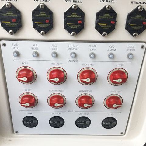
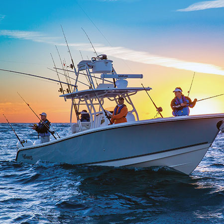
In the above example, when did we realize we had a problem? At a point of catastrophic failure. See pictures of my solution to a similar scenario with another client. The builder of this boat decided to outsource the design and wiring of their battery switch panel and charge combining to another individual. In my professional opinion, the system was designed to fail in more than one regard, and it did, leaving my client in the Bahamas without power for loads, and replacing batteries (at great expense and inconvenience) trying to get the boat operational so as not to ruin the trip. My client was the second owner of the boat, it was 1 year old with roughly 100 hours on the engines when he bought it. What was also concerning was this boat utilized a power steering system that was completely fly-by-wire, meaning it was also completely dependent on a good DC power source. With 4 engines and above 50 mph capability, can you imagine the ramifications of a total steering system loss at above 50 mph? That particular boat sold for north of $1,000,000 when it was new.
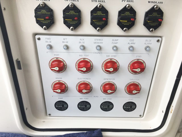
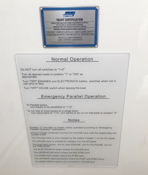
Unfortunately, it was costly for my client, as engineering of a new and proper system was necessary due to the grossly inadequate system installed by the builder. It included all new battery switches, ACR’s, and 2 battery chargers to replace the one totally inadequately sized charger the builder installed. The system I engineered allowed the client to be able run the entire boat (with the exception of the isolated bow thruster bank) from a single bank (if necessary in the case of multiple bank failures). It also provided a detailed placard with proper operation, emergency operation, and basic notes explaining how the system was wired and worked. The ACR’s sourced were installed in a way that allowed easy viewing of their status. As I could easily reference the placard I designed for the system, after sales support was very simple and easy for anything the owner or owner’s representative couldn’t understand.
I apologize if you have read this far and assumed you would know how to properly operate all the switches on your boat after reading this. My intention was to educate anyone reading this to the importance, maybe even life and death importance, of this critical infrastructure to the boat. At the very least, maybe change a day out on the water from a tow in/system failure to a different battery switch selection and party on/address the concern later.